
Getting Started with TrueProp Software...
Some users need a little help getting started - and that's OK! We are here to help you maximize your use of TrueProp!
This brief introduction helps new users understand how to navigate through the TrueProp interface. This includes opening propeller scan projects, reviewing the scan history, analyzing the various graphical views, and generating reports for customers.
This tutorial assumes you have already installed TrueProp Software and the associated drivers before continuing. We also recommend setting your Project and Archive file storage directories from the Tools | Options.... Administrator tab.
This tutorial assumes you have already installed TrueProp Software and the associated drivers before continuing. We also recommend setting your Project and Archive file storage directories from the Tools | Options.... Administrator tab.
|
Run TrueProp and you will see the main screen, PROJECT page.
|
|
|
|
|
|
|
|
|
|
|
|
|
|
|
|
|
Congratulations on completing the introduction to TrueProp!

Learn more: Pitch Distributions
There are many styles of propellers out there - and contemporary propellers have more variation in pitch measurements than traditional flat-face propellers. TrueProp supports both constant pitch and variable pitch propellers. TrueProp also supports both flat and cambered blades (also referred to as progressive pitch propellers).
This section includes guidance for identifying the type of propeller blade you are working on. We will also demonstrate how to setup TrueProp's Reference Targets (REF) for the job at hand.
This section includes guidance for identifying the type of propeller blade you are working on. We will also demonstrate how to setup TrueProp's Reference Targets (REF) for the job at hand.
Pitch Distribution: Constant Pitch or Variable Pitch?
First, let’s review the propeller from the root to the blade tip. On a traditional propeller, we would expect that the section pitch to be the same at all radii – this is referred to as constant pitch. For example, on a 20 inch pitch propeller with constant pitch, the 50R, 70R, and 90R all measure to 20 inches pitch.
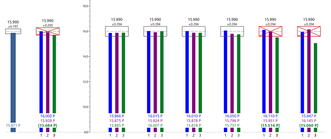
Figure 1 - Constant Pitch pitch measurements from TrueProp Software.
On contemporary propeller designs, the section pitch changes from the root to the tip in order to better match the inflow under the hull – this is referred to as variable pitch. We often see the highest pitch at the 70R, with decreasing pitch at the root and tip. For example, a 20 inch pitch propeller with variable pitch could have a pitch of 19.5 in the 50R, 20.5 at the 70R, and 19.5 at the 90R. The average pitch for the propeller is still 20 inches, but the distribution of section pitch is variable from the root to the tip.
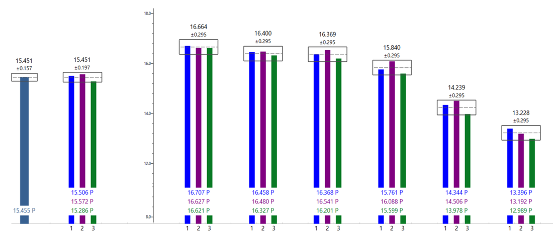
Figure 2 - Variable pitch measurements from TrueProp Software.
Local Pitch: Flat-face/constant pitch or Cambered-face/progressive pitch?
Next, let’s review the propeller from the leading edge to the trailing edge. Again, on many traditional propellers, the propeller face is flat – as a result, the local pitch is the same on the leading edge, the middle, and the trailing edge of the blade. In the previous example of a 20 inch pitch, this means that the first local pitch segment will measure as 20 inches, as will the second and third segments (and so forth). We refer to this as a flat-face/constant pitch foil shape (technically, the term is Ogival).
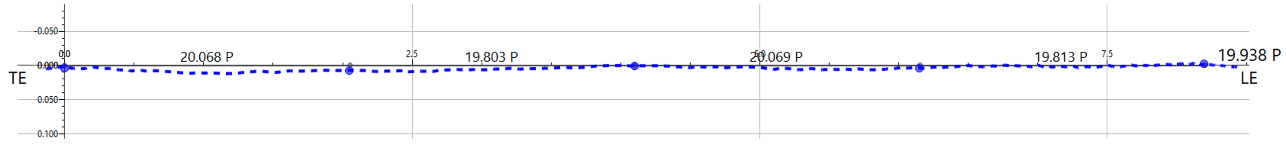
Figure 3- Flat-face/constant pitch 70R line with consistent local pitch values from TrueProp Software.
However, contemporary propellers will have variation in the local pitch from the leading edge to the trailing edge. This is because these propellers utilize camber (additional curvature in the face of the blade) to increase performance. Often, the local pitch increases from the leading edge to the trailing edge – so many people refer to these designs as a cambered-face/progressive pitch.
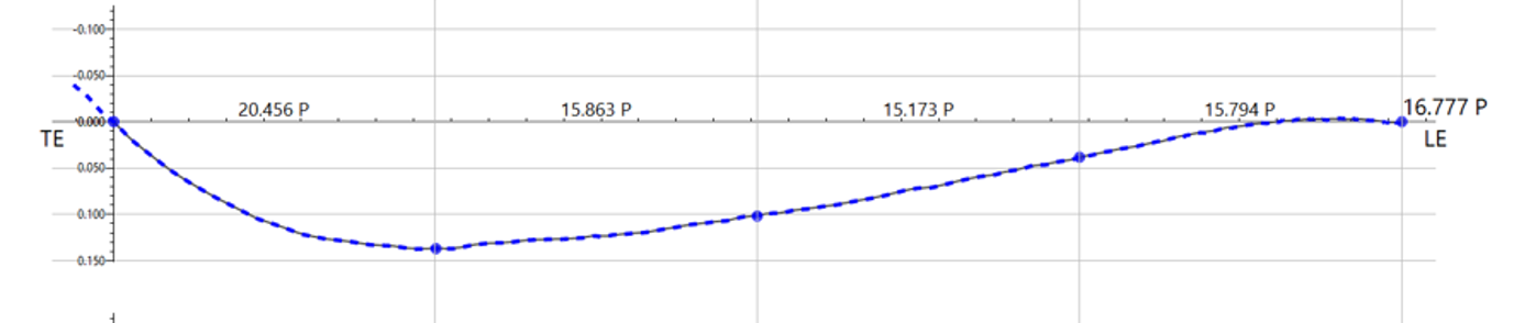
Figure 4 - Cambered-face/progressive pitch 70R line with varying local pitch values from TrueProp Software.
When repairing propellers, it’s important to review and understand the intent of the propeller’s design. Is the variation in pitch due to damage or was that the design intent? Is this propeller a traditional design, where the face of the blade is flat and the pitch is uniform across all radii? That would be a constant pitch propeller with a flat-face… Is there more to the design? Is this propeller a contemporary design, with section pitch varying from the root to tip, like a variable pitch prop? Is there variation in the local pitch from leading edge to trailing edge, like a cambered faced/progressive pitch propeller? These are important questions to answer before you begin reworking the blades!
Example: A Constant Pitch, Flat-Face Propeller
Example: A Variable Pitch Propeller with Camber/Progressive Pitch and Cupping

|
|