Propellers are a critical piece of boating equipment. Many boat-owners know the cringing sound of a propeller strike - whether it’s a log, rope, or running aground, that impact resonates across the deck, through your shoes, and right to your wallet. To get back on the water, you might choose to have the prop repaired at a reputable propeller shop. (P.S. The National Marine Propeller Association, NMPA.org, can help you find a certified shop in your area!) These shops utilize computer-assisted measuring equipment to inspect and repair damaged propellers to better-than-new condition.
It’s often said that propeller repair is a blend of both art and science. This is absolutely true, and experienced repair professionals can save heavily damaged propellers. Many shops, proud of their work, provide inspection reports to customers to document the before and after conditions of the propeller. These reports contain a wealth of information, but many boat-owners have questions when reviewing them. In this article, we will go over the format of a standard propeller scan report, as well as discuss a few tips on how to interpret it. Let’s start with the first part of the report you read, the heading.
The Report Heading
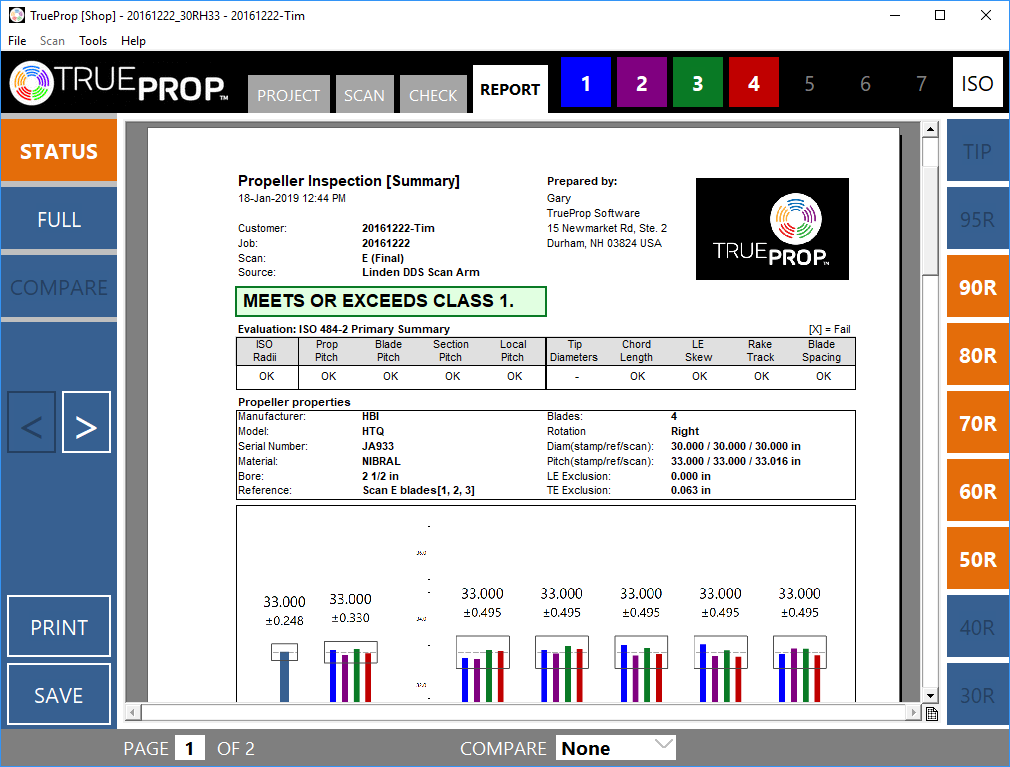
The heading gives information about the repair shop, the customer, and equipment used, as well as the date and whether the report is for the initial condition or the final condition.
Inspection Criteria
When a shop inspects your propeller, most times they are checking the position and size of each blade in multiple locations. The positions and sizes should match from blade to blade, within some acceptable margin. This margin is known as a tolerance. For inspecting propellers, the tolerances for the geometric accuracy are based on the International Standard Organization's rules for propeller manufacturing. The standard is ISO-484 and it has 4 levels of increasingly tighter tolerance “classes”.
The pressure face of the propeller is measured at several pre-defined locations. These locations are described as a percentage of the blade’s length (or more accurately, the blade’s radius). You may see data reported for these positions; for example, “70R” indicates the measurements are taken at 70% of the blade’s length. The higher the class accuracy, the more measurement positions are required.
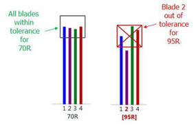
The ISO criteria require inspection of many different parameters of the blades. Propeller performance is greatly influenced by the propeller’s pitch, or the angle of the blade. There is an average pitch for the entire propeller, as well as a pitch for each blade. There is also pitch reported for each blade’s measurement locations (i.e. 50R, 70R, 90R). The reports tend to use Bar graphs to report the Pitch of each blade at the measurement locations (ex. “70R” will have a pitch value and bar graph for each blade). Overlaid on the bar graph results is the tolerance window, which gives us the minimum and maximum acceptable pitch for the desired Class. Measurements of pitch that exceed the tolerance window must be adjusted and repaired to meet the desired Class. The measurement locations (i.e. 70R) can also be broken up into smaller segments to ensure the pitch is consistent from the leading edge (forward edge) of the blade to the trailing edge of the propeller (aft-most edge). This is known as local pitch and is required for the higher repair classes.
While pitch is an important parameter, ISO-484 includes other checks on the blade shape and position. The length of the blade at each measurement location is known as the chord length. Chord length is reviewed because it is important to maintain the same surface area for each blade. The spacing between blades as well as the position of the leading edge of each blade is checked for consistency. Blade spacing is important for smooth and quiet propeller performance. Lastly, the axial position of each blade is checked. This ensures that each blade is raked (or swept backward) the same amount. (This is sometimes referred to as propeller track.)
Compliance Summary
There is typically a statement of compliance (or non-compliance) near the top of the report that gives the overall pass/fail status of the propeller with respect to the desired Class accuracy.
Evaluation Summary
In addition to the overall compliance, sometimes the compliance of an individual criterion (pitch, chord, blade spacing, track, etc.) is detailed. This provides a nice overview of the work required for damaged propellers or the work performed on repaired propellers.
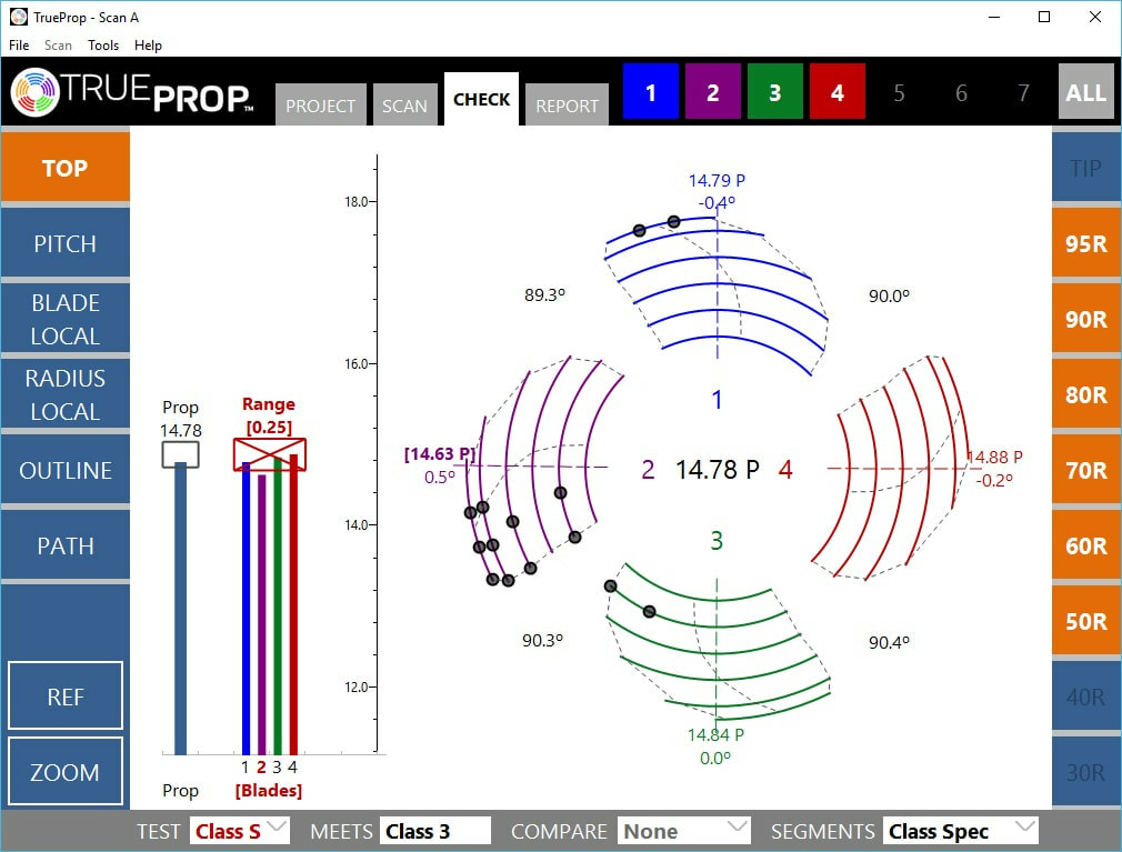
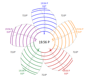
Some software, such as TrueProp, includes a wheel view that displays the shape of the propeller as seen from above. This view is great for finding the damaged regions on the propeller, which are usually marked with a different color or large dot. The wheel view often includes the spacing between blades, as well as reporting pitch values for each blade and the average of the propeller as a whole.
Tabular Data
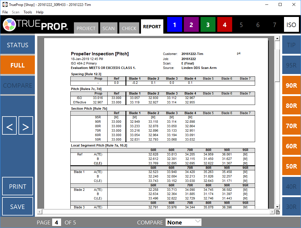
In a full report (not usually provided to the customer), the dimensional values for the blade parameters are listed. The repair technician can compare these values to the expected values in order to determine how to repair the propeller. While this data is extensive and hard for a boat-owner to understand, it is essentially a tabular version of the bar graphs and wheel plot data. If you are interested in learning more about this propeller data, we encourage you to talk with your repair professional or contact TrueProp Software.
They say: “knowledge is more valuable than money,” and
this extends to high-quality propeller repairs
So next time you damage your propeller, remember that often the propeller can be repaired to better-than-new condition by a professional propeller repair shop. The inspection information provided by repair shops can be intimidating and non-intuitive for boat-owners, but a little knowledge about the inspection process and standards can help you interpret your own scan report and ensure your propeller has been repaired to as-good or better-than-new condition.
Download the article, here.


